Sunday, December 1, 2013

Seat Installation

I placed the seats in the car and found a problem with the passenger side. Due to the fact that the e-brake mounting bracket sticks out into the passenger side of the car it requires that the seat be moved closer to the passenger door. The Recaro seats I purchased for this project has a large knob on the side of the seat that hits the side panel of the door. Time to do some cutting.

There is a recess in the side panel that was originally for the retractor of the seat belt. I decided to cut a hole on the back side of this recess to open it up so that the seat handle will fit in the space as well. I decided that I would box this in with 13 gauge plate. Here's the pictures of the holes cut into the side panels. The first one below is the passenger side - the second is the driver's side.


Here's what it looks like after the holes are blocked in. Again, the passenger side is the first picture.


Now the seat belt retractor and the seat handle will both fit into this space. Here;s what it looks like all painted up.


Thursday, November 14, 2013

Extending The Pedals Further

Once the floor pans were lowered I sat the seat in place and found I didn't like the position of the pedals. Even though I had extended the pedals out 1" I felt that it was still too cramp for my long legs. I decided to check out how to add the other 1" shim I had made.

When I held all the pieces in place I saw that the accelerator pedal was going to interfere with the firewall. After a little investigation I saw that I could trim away a little bit of the firewall to make room for full travel. With a plan in mind I got busy at pulling it all together.

I took the two shims and welded them together. I then used a bit of body filler to smooth out the two visible sides of the shim so that it will look great after it is installed. Here's what it looks like after getting it into place.


I did end up having to rebend another tube for the front chamber of the master cylinder. Not a big deal. You can see the larger shim in the left side of the picture. If you want to see what it looked like before I added the second shim take a look at the post regarding the installation of the master cylinder and brake booster.


Here's a shot of what the pedals look like. You can see the notch that I had to cut out for the accelerator pedal. The clutch pedal is still really high since it isn't attached to anything as of yet. I sat on the floor and felt that I had a great amount of leg room. I can't wait to put the seat in place and see just how much leg room is there. I'm sure it won't be Towncar kinds of legroom but every little bit will help.

Sunday, November 3, 2013

Lowered Floor Pans

Ok, how do you fit my 6'5" body into a car designed for the ideal height of 5'7"? Good question. Fortunately this is a question that lots of people a lot smarter than me have considered. Look around and you will find plenty of options to drop the floor pan down to give you more head room.

As I researched the options I found that there are two basic directions to consider. One is to just make a hole in the floor and weld in new pans to give you a place to bolt the seat directly to the floor - maximizing the amount of drop and headroom. A great option is you have standard seats and don't care if you ever have any seat adjustment options. This wasn't the best option for me.

The second option I found was to tilt the back of the floor pan down about 3" so that additional headroom is gained while maintaining the option of seat adjustment. I found quite a bit of good advice on the DeTomaso Pantera Community website - specifically at this post.

http://pantera.infopop.cc/eve/forums/a/tpc/f/6450045562/m/428106782/p/4

Here a gentlemen by the name of Kirk Evans shows a step by step procedure how to drop the pans, angle them back and weld it all back together to give a nice option for gaining more headroom. I believe this option will work with about any seat you use that would normally fit the Pantera. I decided this is how I would modify 3854.

With the website opened on my cell phone, I decided to tackle taking out the driver's side floor pan first. As I laid out the cut on my pan, I decided to modify what I would remove slightly to give me more side to side room for the seats I had purchased for my project (see separate post). In the following picture you can just make out the lines I scribed into the paint of the floor pan showing the approximate position the Evans method outlined in the post mentioned above. By the way the front of the car is facing to the left in this photo - again, this is the driver's side pan.


To make the hole wider I decided to go to the very edge of the pan welds, where the metal doubles over next to the center console and the door jamb. This gave me about 1" more hole width - space I could seriously use. The length of the cut from the doubled piece of metal at the fire wall to the front of the car was 24 3/8 inches. You can see the line scribed in the pan to the left side of the picture above.

After a bunch of double checking it was time to start the cut off wheel. I covered as much of the dash and center console as possible so as to not cause spark damage. The cutting process was pretty simple. There are several places where you will cut into or around support under the car. Kind of a scary process but it works out just fine.

On the left side of the picture above you are cutting into the cross member support that runs from side to side of the car. This is an area you will spend a lot of time welding up a new cross member that should actually provide more support and rigidity that the original design. By cutting no more than 24 3/8" from the back of the car to the front you leave just enough of a lip to give a good welding surface from the remaining floor pan to the new support you will add.

You will have to get under the car and cut into this cross member (the part towards the back of the car) leaving enough metal there to hold your new cross piece. Take a look at the picture below showing what was left after removing the pan.


Unfortunately the sun helps mask what is left on the front of the floor but if you look closely you will see how I ended up cutting the floor pan free. I also cut the rear support just in front of the hole in the upper right side of the picture straight down from the floor. I think the Evans method has you cutting this support at an angle - I decided to cut it straight to give me more options - I will box it in later to add back the rigidity.

This next picture shows the cross member being laid out.


I used a piece of 1x3 box tubing that I had from another project. It isn't particularly heavy but will be very strong once welded into position. You can see how I cut the floor pan and the cross member (the rusted piece below the tubing). By cutting it this way I can weld the top part of the floor to the tubing then take a hammer and pound the cross member up to the 1" side of the tubing and weld it together. This basically takes the cross member and makes it the size of the 1x3 tubing. Very strong!

I cut the 1x3 31" long so as to slide through the cross member under the console support into the cavity under the passenger side floor pan. When I drop that side of the pan I will weld together more 1X3 on that side basically making the cross member one continuous piece. Unfortunately the geometry of the holes opened by the cutting of the floor pan won't allow one piece of tubing to be inserted. You will have to cut it down and reweld it back together after it is placed.

The 31" piece I used also had to be cut in half to get it inserted properly. The piece that goes under the console support had to be notched to make room for the coolant pipes and the vacuum pipe that runs the length of the car. Here's a picture showing the beginning of the welding process.


You can see next to the clamp at the top of the picture where I welded the two pieces of tubing back together after inserting the one piece under the center console support. You can also see the weld at the top left of the picture where the floor is being welded to the tubing. I inserted thin metal into the gap that resulted from the difference in height between the 1x3 and the remaining floor to give me a decent place to weld to. filled all other gaps with appropriate sizes of triangle pieces of metal and boxed in almost everywhere left opened by all the cutting I did. 

The last weld I did was to join the bottom of the original cross member with the 1x3. I beat the bottom part of the metal I left on the cross member up around the back side of the 1x3 and welded the two pieces together 

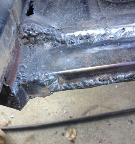
Here's some pictures showing the finished cross member welds.


The bottom weld in the picture below shows where I welded the 1x3 to the remianing metal left on the bottom of the cross member cut. All gaps were welded with cut metal to box in allow openings. This gives you a good strong support. Some smoothing of welds will be required but not much since most of the weld will be hidden by the new floor pan.


The openings in the picture below will be closed by the new floor pan. I decided not to box these in yet since they will interfere with the fit of the pan I will be adding later.


Next I used 13 gauge sheet steel to make the floor pans. This is definitely over kill in the size but I wanted the pans to be very rigid. I first started by cutting and welding up the piece that will be at the back of the floor. This is what gives me the drop I wanted. I decided that 3" is what I'm going to live with. 

I cut a piece of sheet the length of the opening and cut it 4.5" wide. I wanted the extra 1.5" to be a support for the floor pan itself. I bent this piece at the 1.5" mark so that floor would be 3" dropped at the back of the pan. 


The 90 degree bend isn't exactly the angle that I will need to mate up to the floor pan. I will bend it up to match the pan when the pan is welded in place. This design will help hold the pan in place and give two good welding surfaces to secure it into place. I also welded the original support that I cut when removing the plan to this new piece added to the Pantera. 


Next came the pan itself.  I simply measured the opening that was cut and added 1/4" for the bends that I wanted to add to shape the pan into place. I ended up cutting most of the 1/4" away to make it fit properly. This shot show the pan welded into place.


This is the only place I ended up giving the pan a bend. I wanted the floor new pan to blend in with the original pan so I gave it s slight bend to match up to the 1x3" cross member added earlier. This really gave it a good fit and look. 


Here's a shot under the car showing the lip that I bent up to meet the pan. With the pan welded on the top side it was easy to use a hammer to shape the bottom lit to match pan easily. This really gave the pan a solid feel.


Then it was just a matter of making the side pieces and welding them up. I used a piece of cardboard to cut the shape needed to fit perfectly and cut out the sheet using the template. Here's a shot of the one side welded up. 


A bunch of welding wire later it's done. I have to say I like how it all came out. 


Unfortunately nothing can mask the fact that the pan was dropped. Here's a shot from under the car. 


Best part is that I sat in the floor and WOW what headroom. I really like how this all came out and am looking forward to mounting the seat rails and seeing how the seat actually fits the new pan. Now onto the passenger side. 

Here's the passenger side completed. 


The biggest challenge was to get the e-brake bracket boxed in. I sat the new seat into the hole and found that I will need to do a little trimming on the door side of the side rail. The dial that lays adjusts the seat back interferes here. I think by taking away some metal near the hole that is already there will fix this problem completely. Here's how I decided to box in the e-brake support. 


Later I will prime and paint the entire surface. The next step is to install the seat rails. That will be in a separate post. 

Thursday, October 31, 2013

Purchased Seats

Like most of 3854, the seats for my Pantera are MIA. That's OK because I wanted something different anyways. I have been looking at seat options and found two options that caught my attention. You can read all about the various options people have considered in the thread below.

http://pantera.infopop.cc/eve/forums/a/tpc/f/6450045562/m/231109126/p/1

The two options that I decided to take a look at were the Fiero seats (with mrmikes.com) and the Corvette seats (Gary Harrig option). Both of these options seemed to have manufacturers who supplied nice options for covers and complete seat purchases. I decided I liked the Harrig option best and contacted him only to find out that due to arthritis, Mr. Harrig doesn't make the seats any longer. Bummer.

I liked the Fiero seat option as well since covers were available for a good price at mrmikes.com. As I was doing a search on ebay and craigs list for used Fiero seats I came across this ebay vendor.

http://www.ebay.com/usr/zoomzoomzoom-ing

He had a big selection of seat covers and actual seats that he was selling for Posche and BMWs. He also had several Porsche seats that could be purchased with 7 days lead time. When I was looking he had a set of Recaros out of an older Posche that looked perfect. They cost $1,150 recovered and in like new condition. His factory is located in Glendale  and he lives in Seal Beach CA. Seeing that Seal Beach is only 65 miles from my house, I met him there to take a look at the seats. I loved them and bought then - they look fantastic. Here's a few pictures of the seats. They should fit just fine. More to come on that when I get the car's floors prepped for installation.


Tuesday, October 29, 2013

Dash Finishing

I really liked how the console came out with the fiberglass applied. See that post for the materials used to finish this part of the interior. The same process and materials will be used for the dash assembly itself.

To start the dash I took it out of the car. To do so I have to remove the dash front and take it out separately from the dash top. Once the assembly was removed I started the glassing process.

First I sanded down all the sharp edges. I wanted smooth curves for all the dash top and front. I used a RO sander with 80 grit paper to round the edges. Once cleaned and prepped I layed two layers of fiberglass. I found from working with the glass on the console that it is best to lay the flat surfaces first then come back and do the rounded areas later. This gives a much smoother final product and makes for less patching later. Bubbles in the cloth is still a problem but I'm hoping that will go away the more I work with fiberglass. Bubbles just mean more sanding and bondo - not a big deal but takes time.

Here's couple shots of the dash top fiberglassed. Not much to look at but that's how it starts. Lots of sanding ahead of me.


At the same time I glassed the two bottom sections of the dash to be ready to prep them while I sanded on the top. Here's how they look with two layers of fiberglass bonded down. Notice the rounded edges. The fiberglass really brings those out and makes it look really good. 


This shot of the dash top shows how it got the curve on the top I was looking for. I used the canned spray foam called "Good Stuff" (from Lowes) and sprayed the entire tip with a good helping of the stuff. This stuff is really sticky and adheres to the plywood really well. Once good and dried I took a grinder with a sandpaper attachment and shaped the foam roughly like I wanted it. This is what will shape the fiberglass. Here's what the foam looks like on the board top.


After two layers of glass it was time to sand and bondo. It probably spend three days solid working on the dash top to get it looking smooth. There are still a couple of pin holes that need to be filled but that will come before the final paint is applied. 

Here's the progress pictures. The first picture shows the fiberglass covering. The second picture shows the bondo application on one end. 


Here's a couple of photos showing the top sanded and primed. Still a few small places to touch up but it's looking pretty good. 


Here's the two bottom pieces of the dash also sanded and primed. 


Finally the day came to put the dash back into the Pantera. I knew that there would need to be some touchup here and there to make it fit again, but I was amazed how easy it came together.  Here's a bunch of pictures of how it looks put together. 


Still need to figure out what parts will be covered with leather and which pieces will just be painted. For now I think I'm done working on this this part of the project. I still need to install some defroster vents on the top of the dash. That'll happen later. 

Rear End Rebuild

It's a shame that changing the rotors on the Pantera is such an involved process. The rotors on mine are in terrible shape - warped and mismatched. Not something I want to deal with.

I have a new set of Wilwood rotors ready to install but Wow De Tomaso didn't make it easy. Here's a great outline of how to tear down and rebuild the rear knuckle.

http://www.panteraplace.com/page87.htm

Here's a couple before shots. You can see how badly the rotor is rusted. Not a big deal, but try to spin this one and you can quickly see how warped it is.


I removed the knuckles (uprights) and had them sitting in my garage for a few weeks. I was planning to take them to the shop where I was going to get the half shafts rebuilt but Christmas got in the way. As usual, I decided that I just wanted to see if I could take care of the upright rebuild myself. Big problem - no press. 

So after looking at a few presses on Craig's list I decided I could make one myself. Out came some scrap metal, a couple C-clamps, two 4x4s and an old 4 ton bottle jack. Here's a picture of one of the uprights in my "back-woods" press. 


As you can see from this picture, the rotors are missing. That's because I pressed out the shaft using the rotor as the bracing point on my 4x4s. Once the shaft was out I was able to discard the warped and worn rotors.

Upon inspection of the bearings I saw that they looked pretty good. Obviously the previous owner had put in new bearings. Since I had already ordered a new set I decided to change them anyway. Glad I did, one of the uprights wasn't quite put back together right and the spacer between the inner and outer bearing was really loose.

Back to my home made press and out came the old bearings and in went the new. I'm really happy to have been able to do this work myself. Saved a bit of money and learned how to do it for future reference.

I started to but the uprights back together again and found some of the old wheel studs worn too much to reinstall. They spun in the holes - no way to put on a lug nut unless it holds after pressed into place. After searching a few of my favorite parts stores I found that I needed to purchase them online. One of the Pantera parts places has the for a mere $15 EACH!!!! Ouch. I need 10. Plus it takes 4-6 weeks shipping. Not in the cards for me.

I did a little digging and found several wheel studs in a box of parts. Then I saw an old front rotor with new studs in them. I pressed them out and found that all the ones I found worked great. So, I started putting it all together - then I found another issues. The flat place on the wheel stud that was put there to keep it from spinning in the hole didn't come into contact with anything on my new Wilwood rotors.

To fix this problem I decided to weld a tab on the wheel stud so it would give me the holding power needed to keep the stud from spinning. Here's a picture of the finished product.


After getting the studs right it was a pretty easy job of pressing in the shaft assembly. Here's several pictures of the finished product.


I finally found a tool on line to tighten up the nut on the rear hub. Now I had to figure out how to put 300 ft lbs on that nut. Here's what I came up with. I decided to strap the tire and wheel to a frame I had laying around. I then bolted the hub to the wheel. This let me hold the hub securely in place.

I took out my 3/4" ratchet and put that on the tool that I bought. The ratchet is 1.5 feet long. That means that I need to put my entire 230 lbs on the ratchet to get over 300 lbs of torque on the nut. To make this a little easier, I put an 8' bar on the ratchet. With that 8' bar it only takes less than 40 lbs to get the desired 300 ft lbs of torque. I used the long bar to get the nut very tight. I then removed the bar and put my entire weight on ratchet. Here's a couple of pictures of the set up I used to get this job done.


After having the rear out of the Pantera for over two months I finally got to bolt it all back in. Here's the pictures of what it looks like completely in place. You will notice the e-brake set-up is somewhat different than stock!!! I used WILWOOD MC4 MECHANICAL PARKING BRAKE CALIPERS FOR 0.81" WIDE DISCS to make my e-brake work. They are very economical and a nice small package. Straight out of the box it is a very tight fit onto the rotor. I decided to take the caliper apart and do a little grinding to allow the pads on the e-brake to open up a bit more. That solved the tight fit problem nicely.