The wiring was a multi-month process. What I'm going to do here is to highlight the end result. I'll show you all the relays, connections, fuses and other wiring issues I had to deal with to make this think go.
As you may remember, I decided to work this Coyote swap on a budget. I bought the engine out of a totaled 2012 F150 for just around $3700. The engine came with the AC pump, Alternator, Computer, and Engine Wiring Harness. I had to find the other two harnesses/connectors from online sources and junk yards. I was able to get both harnesses for just under $150.
I also bought a 2012 Coyote wiring book from Ford. This thing is a real pain in that wiring is broken down into smaller components so you are required to flip from page to page trying to ID all the connections that need to be made. I was also able to get a more usable wiring diagram from a friend of mine that made tracing wires a bit easier. Between the two resources I was able to fabricate all the wiring connections and runs necessary.
Keep in mind, my car is a junk yard rescue. Everything was missing in my car. Not a single wire was there so I had to run everything. My routing might not be stock but I had to make do with trying to figure out how to get my wires from point A to point B on the car. For all you lovers of everything stock, I'm sure what I did will end up pissing you off, but necessity is the mother of invention and I was presented with a whole lot of necessity with my car.
The basic wiring kit I used is from a company called Hot Rod Wires. See my post called Wiring for details on this process. I decided to use the front boot as my main wiring junction. I fished all my wires to the Hot Rod Wire fuse box and mounted it to a custom made "shelf" in the very front of the nose. This shelf will hold all the other components (rely boxes and other fuses) that I will need to make this thing come to life. Here's a shot of what I made with everything mounted in place.

I'll take time to explain what everything does as I present more of what I did to get her wired up. Starting from the passenger side you have the Hot Rod Wire fuse box, an additional fuse box controlling much of the engine wiring and two relay/fuse boxes. These boxes were pulled from early 2000's Mustangs from a junkyard near me. I rewired them to make them work for what I needed in the Pantera. Also refer to the earlier post called Wiring where I explain how I wired up the headlight doors using the junkyard relay box shown on the far side of the picture above.
I decided to mount the computer on the firewall I built behind the driver's seat in the engine bay. This gave me a good place to run all the necessary wires to the computer and made the harnesses fit just right. I had to do quite a few wire connections to get her all hooked up. I will do my best to present all the wiring connections needed to make the Coyote start up.
Here's a picture of the computer mounted in place. Keep in mind I haven't take the time to pretty up all the wires. That will come much later when I know I won't be needing to run any more wire. One day it will look much less of a rat nest. I have learned from past wiring projects, don't tie everything off until you are sure you are done running wire. Otherwise your nice neat bundles start to look like a bad hair day.

Now for some wiring info. I created a couple table showing the wiring harnesss for the Coyote. I pulled some of this info off various sites and modified to add what I did to get it wired up. The first one is what I call the 581Harness from Ford. This one is the non-engine wiring harness. It is a 70 pin connector. The following table highlights what each pin is wired as out of the connector from Ford and what wires I connected to that pin. Where the pin is struck through is pins that I'm not using. The Dia Page column shows what page the connection can be found on in the Ford Wiring book mentioned earlier. The notes give more detail on what this pin does and how I wired it up.
The engine wiring harness is almost completely wired to the connector. Only the 4 wires shown above had to be connected from the 581 harness to the engine harness. The explanation above shows how I did this.
Then there is what I called the 15525 Harness. This normally would have gone to the transmission and to other components like the O2 sensors. Most of these wires go unused but some have to be connected. Here's a table like above showing how I wired this up. Again, the items that are crossed out are not used in my application. The wires are long enough to hook directly up to what I need them to go to so the Ford Color is the same as My Color when it comes to the wiring.
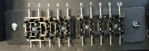
These last five wires were not in the connector but had to be wired as shown. The following table shows the two fuse blocks and how they are wired up. The photo below shows the numbering scheme on the blocks.
Fuse 1
|
15a
|
Power In Jumper 1-5 off 87 of PCM relay.
Out, White->Pin 67&68 of 581 harness
|
Fuse 2
|
15a
|
Power In Jumper 1-5 off 87 of PCM relay.
Out, PNK/OR->OR/GRN 8 conn->GRY/OR->MAF power pin 3 MAF conn
|
Fuse 3
|
15a
|
Power In Jumper 1-5 off 87 of PCM relay.
Out, GRN/YEL->GRN/BLU->WH/GR->WH/LtBLU 8 wire conn->VIO 4 wire 581
|
Fuse 4
|
10a 13-5
|
Power In Jumper 1-5 off 87 of PCM relay.
Out, Tan->86 of Cooling Fan Relay#3 in front power box
|
Fuse 5
|
15a
|
Power In Jumper 1-5 off 87 of PCM relay.
Out, YEL->YEL/BLU->GR->GR/OR 8 wire conn->LtGR 4wire on 581 harness
|
Fuse 6
|
10a
|
Power In BLK/YEL from hot thd stud on Alt - Hot at all times - Out, OR->VT/OR Pin 35 581 Harness
|
Fuse 7
|
10a
|
Power In BLK/YEL from hot thd stud on Alt - Hot at all times. Out, BLK/WHT->YEL/RD Pin 62 581 Harness
|
Fuse 8
|
Empty
| |
Fuse 9
|
5a
|
Power In YEL/GRN hot start and run off ignition switch
Out, 5a->OR-BLU->pin 42 581 harness
|
Fuse 10
|
15a
|
Power In, PUR Start only HRW Harness through 15a fuse Out, PUR->BLU-WHT Pin 16 581 harness
|
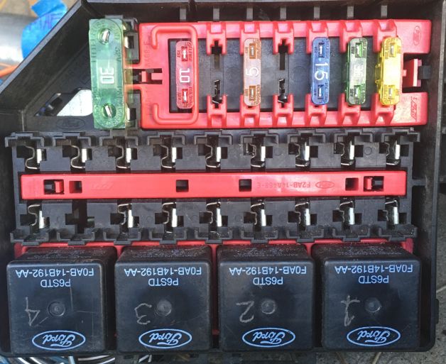
Finally there is the relay box in the middle of the boot. This is used to control the feeds to the fuel pump and the PCM, both of which require relays. Two of the relays remain open as does most of the fuse slots. This gives room for future expansion.
Here's a shot of the relay box mounted in the Pantera.
Fuse 1
|
WH/RD - Feeds #3 on Alt Conn
|
10a fuse
|
Fuse 2
|
Feeds 30 on relay 2
|
open
|
Fuse 3
|
Feeds 30 of relay 3 - Fuel Pump Relay
|
15a fuse - fuel pump
|
Fuse 4
|
Empty - no wires
|
n/a
|
Fuse 5
|
OR->TAN
|
15a fuse - To data link connector (ODB test port) Pin 16
|
Fuse 6
|
Empty - no wire
|
n/a
|
Fuse 7
|
BLK/WHT wire
|
n/a
|
Fuse 8
|
Feeds 30 and 86 of relay 4 - PCM Relay
|
30a fuse
|
Relay 1
|
|
not used now
|
Relay 2
|
|
not used now
|
Relay 3
Fuel pump
|
|
Fuel Pump Relay
|
Relay 4
PCM
|
|
PCM Relay
|
I know this is a bunch to digest but all I know it works. What I did to try and help me make sense of it all was to make my own wiring diagram. The graphic below shows it all brought together.

Anywhere you see Start Only or Start/Run Only, this was hooked up to the Hot Rod Wire system coming off the ignition switch I modified for the Pantera. See my separate post on wiring up the modular ignition switch I used for this project.
The last thing that I had to to was to pay someone to turn off many of the circuits in the computer that I wasn't using. I believe that there is a lot of anti-theft components in the original wiring that I'm not using. When I went to first start the Pantera, all the engine components (injectors, coils, fuel pump, etc.) went completely dead. In the Run position it all showed hot, but in the Start position, nothing. After a bunch of wire tracing and reconfirmation I had the wiring right I found out that the computer was shutting everything down because it sensed too many things missing in my setup.
When all the extra components were turned off in the computer (I'm not sure I'm using the right terminology but that's what I think was done), the cart fired up right away!
Here's a link to a video of that amazing day. Keep in mind this is the first time in over a year the engine had been started. It cranks a bit before firing up but that's because the fuel system and everything was never tested. She now cranks pretty quickly. It still needs to be tuned for idle and proper accelerator pedal sensitivity, but as of this date it is running amazingly well for having been transplanted like it has been.
Video Link
https://www.youtube.com/watch?v=QJtKOvW2XI4