Tuesday, August 20, 2019
Some Update Photos
Every now and again you just need to stand back and take a look at the progress. Here's some shots of what she looks like as of 8/20/19 - 6 years into the project.


Thursday, August 8, 2019
Updated Fuel System
I have posted a couple blogs on the fuel system. In the past I custom made a fuel tank and plumbed it up to be filled in a vent through the passenger side back window. Although I really liked this set up, I found out the hard way that maintenance is a big issue with this original design. You can check out what I originally did by visiting these posts.
After fighting to get my custom made fuel cell out of the car to replace a faulty fuel pump, I decided to give up my "boot space" in the back of the car for a purchased fuel cell. The cell that fig amazingly well was a 15 gallon, aluminum cell I purchased from Summit. Here's the Summit details.
Summit P/N RCI-2162A. The Manufacturer P/N is 2161A. This cell requires an external fuel pump and has a 0-90 Ohm Sender for my fuel gauge. The dimensions of the cells are 30" wide, 12"deep and 9" tall. The cell cost $250 after taxes and handling. They shipped it to me in one day!
I got to work making a cradle to hold the tank in place. I used some angle I had laying around to form the base and locking straps. It came out really nice. Here's a couple shots of the tank in place.
The black painted mounting bracket offset by the silver of the aluminum tank really looks nice. The fill nozzle is on the right in the photo. The device on the left of the top of the tank is the sending unit for the fuel gauge. The red capped ports are the vent (top), return (left), pickup (bottom). They are all AN-8 fittings.
You will notice that the throttle body for the Coyote engine is not connected to my filters. I will have to rework the mounting system to accommodate the location of the fuel tank. You can check that out at my post here (
To attach the tank assembly to the car, I decided to custom make some brackets underneath the mounting cage. The photos below shows the four mounting points. The passenger side is show first with the driver's side shown second.
Here's a shot from the passenger side of the car looking down on the tank. I tried to hide the mounting brackets as much as I could.
Next comes the installation of all the various components. I'll follow up on this post as I get time to add the fuel pump, filters and regulator. Check back for more.
- https://johnspantera.blogspot.com/2014/09/fuel-tank-fill.html
- https://johnspantera.blogspot.com/2014/08/fuel-tank-pump.html
After fighting to get my custom made fuel cell out of the car to replace a faulty fuel pump, I decided to give up my "boot space" in the back of the car for a purchased fuel cell. The cell that fig amazingly well was a 15 gallon, aluminum cell I purchased from Summit. Here's the Summit details.
Summit P/N RCI-2162A. The Manufacturer P/N is 2161A. This cell requires an external fuel pump and has a 0-90 Ohm Sender for my fuel gauge. The dimensions of the cells are 30" wide, 12"deep and 9" tall. The cell cost $250 after taxes and handling. They shipped it to me in one day!
I got to work making a cradle to hold the tank in place. I used some angle I had laying around to form the base and locking straps. It came out really nice. Here's a couple shots of the tank in place.
The black painted mounting bracket offset by the silver of the aluminum tank really looks nice. The fill nozzle is on the right in the photo. The device on the left of the top of the tank is the sending unit for the fuel gauge. The red capped ports are the vent (top), return (left), pickup (bottom). They are all AN-8 fittings.
You will notice that the throttle body for the Coyote engine is not connected to my filters. I will have to rework the mounting system to accommodate the location of the fuel tank. You can check that out at my post here (
To attach the tank assembly to the car, I decided to custom make some brackets underneath the mounting cage. The photos below shows the four mounting points. The passenger side is show first with the driver's side shown second.
Here's a shot from the passenger side of the car looking down on the tank. I tried to hide the mounting brackets as much as I could.
Next comes the installation of all the various components. I'll follow up on this post as I get time to add the fuel pump, filters and regulator. Check back for more.
Wednesday, June 19, 2019
Window Regulators
This one just about broke me! I went as far as to put my Pantera on "double secret probation." Basically, I was about to raise the white flag if I couldn't get the windows to work without having to scrounge for parts that are worth their weight in gold. You have to remember, this is a junk yard find that I'm trying to bring back to life without spending a fortune in the process. Finding all the parts necessary to make the windows work is an expensive proposition. If I couldn't come up with a workable alternative, I was ready to just give up on the old girl.
I started off this journey with going to the local junk yard and pulling some regulators out of a 2000 Mercury Cougar. By the way, I pulled the glass from this car thinking that I will be able to cut it down to make my own side glass. I'll discuss that in another post. I also pulled a completely different regulator setup from a 2003 Ford Focus.
I went to town on the Cougar regulators first. I did a bunch of modifications to the regulator and to the inside of the Pantera door. I messed with it for over a week before tossing in the towel. I just couldn't get the geometry to work right and get the electric motor to fit inside the door. Nice try but the Cougar just won't work - at least with the mods I did to it.
I then tried the Ford Focus version. This one had to be cut down about 4 inches. After making this modification I could never get the pull wires to reconnect properly. Another week later, I ended up tossing this one in the trash as well. Now I was bummed! What was I going to do?
I did a bunch of searching on the Internet and found this post. https://pantera.infopop.cc/topic/window-regulators-from-ford-transit-eu
A guy had used the window regulator from a European Ford Transit (2002 MK6). I jumped on Ebay and searched for that part and found a passenger side (our driver's side) part, with the motor in England for the equivalent of $65 shipped!!! What the heck. Let's give it a try. I ordered the part and two weeks later, had it in my hands. You gotta love modern technology.
The guy on the pantera.infopop post gave some general, not too detailed instructions on how to modify the Transit part to make it work for the Pantera. The long and short of it all is that I was able to get it installed and it works. Here's a video of my driver's side regulator working. I'm so excited.
With a little bit more careful grinding I was able to peel away the rest of the arm off the sprocket. I will need to repair the areas where I ground a little too deeply. Nothing a little weld can't fix. The following shot shows what the assy looks like with the arm completely removed.
On the picture above I also marked the locations I will use to mount the regulator to the Pantera. The top two holes had rivets in them. For the third mounting point I had to add a bit of metal to cover an existing hole and make room for the new mounting hole. The two photos below show you what I did to prepare the assy for mounting.
Here's the other side of the assy.
In the next shot you will see the regulator assy installed in the Pantera. You are looking at the driver's side (left) door. The front of the car is to the right of the picture. I have labeled three points of interest I want to highlight.
Let's start with Point C. I highlighted this area to show you how I aligned the assy in the car. The guy in the post I first saw describing how to modify the Transit regulator for the Pantera seemed to have the assy aligned as shown in my photo. I tried to get the lower section of the assy to be as straight as possible with the door line shown by Point C. I also tried to make the horizontal as close to the edge of the door frame perpendicular to the door line indicated by Point C, Hard to explain. Just try and get the regulator to line up closely as shown in this picture.
Point A shows the back mounting hole. This is the part of the regulator where I added the tab to cover an existing hole and make a new one - see previous two photos. You will notice I modified the door to inset the nut for this hole (Point A). I did this when attempting to mount the Cougar regulator. You will notice two more inset modifications and a bunch of other holes that shouldn't be there. All this was done to try and make the Cougar regulator work. I'll be doing some repair work to make it look less like Swiss cheese.
Point B shows the mounting holes for the front of the regulator assy. You will notice that I welded in a piece of plate to cover the access hole that was in the door. I wanted a pretty strong mount so I decided to just close up this access hole all together,.
With the regulator assy in place, I could now start to figure out how to reattach the arm in the right position. Here's where marking the open position becomes very important. You can see the word "UP" marked in the very center of the regulator assy in the photo above. This shows me that I have the geared sprocket in the right place.
From there I held the arm up to the approximate position where the window will be when in the full open position. I marked the arm on the sprocket in this position as best as I could. I pulled out the regulator assy and tack welded the arm into position. I then carefully placed the assy with the arm tacked to the gear sprocket back in the car. You will note there is some interference between the arm and the rest of the window mechanism when in the full up position. We will take care of that in a minute. Make sure that the arm is in the right position to give you full travel up and down. You have to eyeball it a bit here due to the arm being too long and some interference here and there.
In my first test fit, I found that I had not quite gotten the position of the arm correct. It wouldn't quite go up all the way up as I had tacked it together. I ground the arm off and retacked it. I put it back in the car and it was just right. Now to take care of that interference issue.
The guy in the original post said to make an S-bend in the arm to make room for it to travel without interference. He decided to make the S-bend at a point closest to the geared sprocket (see the photos on the post I linked earlier). I decided to make the bend a bit further down the arm itself.
The arm is pretty stout. To make the bend easier I cut 2/3 rds of the way through the arm in two places about 2" apart. I bent the first cut out and the second cut back in to give me the clearance needed. See the photos below to get an idea of the size and angle I used to bend the arms. You don't have to be exact here - you can tweak it as you go.
When I was happy with the angle, I tacked it up. I didn't finish weld it just in case I needed to make more adjustments later. Amazingly, the bend was pretty dead on. A couple of tweaks later I was happy with how the arm seemed to be able to move from fully up to fully down.
Last step was to put an end on it to attach the regulator to the rest of the window mechanism. Fortunately, I had all the window sliding parts for the driver's side door. The passenger side, I wasn't so lucky. I already made a new sliding bar for the passenger side window using the stock driver's side as a template. I'll show you that project in another post. The sliding assy is also missing for the passenger side. I'll have to make one of those as well using the driver's side as a guide. That too will be another post down the road when I get time to take on that project.
The sliding assy has an articulating arm that gets attached to the regulator arm. The mounting point is a 1/2" threaded stud that stands 1/4" off the sliding assy. I took a piece of 1/4" flat plate and drilled a 1/2" hole in it. I ground it down to match the contour of the sliding assy mounting point. I then carefully measured how long the regulator arm needed to be in order to go fully open and closed and cut it off. I removed almost 4" of the regulator arm itself. How much you take off will depend on how long you make the mounting point for the slider assy.
When I felt that I had everything measured properly I tacked the mounting piece to the regulator arm. Here's three shots the new mounting point tacked to the regulator arm.
When I was happy with how everything looked, I finished welded it all up, ground it down and reattached the motor to the assy in the open position. Note: it is a lot easier to get the regulator into and out of the car when it is it is in the full open position.
After the motor was attached, I carefully greased all the moving parts and tracks. I then got a battery out and gave it a try. The result is shown in the video I included at the beginning of this post. This last shot shows you the regulator installed with the window in the full open position.
I quickly got back on Ebay and ordered the regulator for the other side. I found another one from England so I ordered the driver's side (our passenger side). When I get that one, I'll remove the one I modified and copy it as closely as possible. I will also mount the passenger side as close to the points I mounted the driver's side.
If your regulator has gone bad, this is a really inexpensive and relatively uncomplicated modification. I'm so glad I came across this option. I might not have wanted to continue if I couldn't get the windows to a place where I might be able to get them working. One big step forward!
I started off this journey with going to the local junk yard and pulling some regulators out of a 2000 Mercury Cougar. By the way, I pulled the glass from this car thinking that I will be able to cut it down to make my own side glass. I'll discuss that in another post. I also pulled a completely different regulator setup from a 2003 Ford Focus.
I went to town on the Cougar regulators first. I did a bunch of modifications to the regulator and to the inside of the Pantera door. I messed with it for over a week before tossing in the towel. I just couldn't get the geometry to work right and get the electric motor to fit inside the door. Nice try but the Cougar just won't work - at least with the mods I did to it.
I then tried the Ford Focus version. This one had to be cut down about 4 inches. After making this modification I could never get the pull wires to reconnect properly. Another week later, I ended up tossing this one in the trash as well. Now I was bummed! What was I going to do?
I did a bunch of searching on the Internet and found this post. https://pantera.infopop.cc/topic/window-regulators-from-ford-transit-eu
A guy had used the window regulator from a European Ford Transit (2002 MK6). I jumped on Ebay and searched for that part and found a passenger side (our driver's side) part, with the motor in England for the equivalent of $65 shipped!!! What the heck. Let's give it a try. I ordered the part and two weeks later, had it in my hands. You gotta love modern technology.
The guy on the pantera.infopop post gave some general, not too detailed instructions on how to modify the Transit part to make it work for the Pantera. The long and short of it all is that I was able to get it installed and it works. Here's a video of my driver's side regulator working. I'm so excited.
I decided to take a bunch of pictures to try and give a few more details on how to modify and install the Transit MK6 regulator for your Pantera. I don't have exact measurements since they will depend on how closely you place the regulator assembly to the same place I installed mine. I think that you will be able to pretty much figure it out if you follow my general steps below.
First thing you need to do is to remove the electric motor. Before you do this, make sure the regulator is almost at the full open position. I stopped the regulator from going to full open because I wanted a couple extra teeth available for any mistakes I made along the way. I'd rather it stop before the end of the sprocket than it run out of travel before the window is fully closed. Be sure to mark the this open position so you can get back to it after the motor is removed.
To remove the motor, use a T20 driver and take off the exposed screw closest to the sprocket gear (you can't get to the other one until you close the window). With the one screw removed, apply power to the motor and close it. This will expose the second screw near the gear portion of the sprocket. When that screw is removed you can take out the last one. With a little wiggle you can pop the window motor off the sprocket. Set it aside and save the mounting screws. By the way, the applying the positive to the red wire opens the window. Applying power to the blue wire closes the window. At least that is how it worked on my part.
Next I removed the arm that comes off the geared sprocket. I began drilling out the 4 weld points that holds the arm to the geared sprocket. This turned out to be a more challenging job than I thought. I simply could not get the weld fully drilled out. So I grabbed the grinder and began carefully cutting around the holes to help persuade the arm to come off the sprocket. This too didn't work all that well. So, I cut the arm off. Here's a shot of the regulator assy with the arm missing.
On the picture above I also marked the locations I will use to mount the regulator to the Pantera. The top two holes had rivets in them. For the third mounting point I had to add a bit of metal to cover an existing hole and make room for the new mounting hole. The two photos below show you what I did to prepare the assy for mounting.
Here's the other side of the assy.
In the next shot you will see the regulator assy installed in the Pantera. You are looking at the driver's side (left) door. The front of the car is to the right of the picture. I have labeled three points of interest I want to highlight.
Let's start with Point C. I highlighted this area to show you how I aligned the assy in the car. The guy in the post I first saw describing how to modify the Transit regulator for the Pantera seemed to have the assy aligned as shown in my photo. I tried to get the lower section of the assy to be as straight as possible with the door line shown by Point C. I also tried to make the horizontal as close to the edge of the door frame perpendicular to the door line indicated by Point C, Hard to explain. Just try and get the regulator to line up closely as shown in this picture.
Point A shows the back mounting hole. This is the part of the regulator where I added the tab to cover an existing hole and make a new one - see previous two photos. You will notice I modified the door to inset the nut for this hole (Point A). I did this when attempting to mount the Cougar regulator. You will notice two more inset modifications and a bunch of other holes that shouldn't be there. All this was done to try and make the Cougar regulator work. I'll be doing some repair work to make it look less like Swiss cheese.
Point B shows the mounting holes for the front of the regulator assy. You will notice that I welded in a piece of plate to cover the access hole that was in the door. I wanted a pretty strong mount so I decided to just close up this access hole all together,.
With the regulator assy in place, I could now start to figure out how to reattach the arm in the right position. Here's where marking the open position becomes very important. You can see the word "UP" marked in the very center of the regulator assy in the photo above. This shows me that I have the geared sprocket in the right place.
From there I held the arm up to the approximate position where the window will be when in the full open position. I marked the arm on the sprocket in this position as best as I could. I pulled out the regulator assy and tack welded the arm into position. I then carefully placed the assy with the arm tacked to the gear sprocket back in the car. You will note there is some interference between the arm and the rest of the window mechanism when in the full up position. We will take care of that in a minute. Make sure that the arm is in the right position to give you full travel up and down. You have to eyeball it a bit here due to the arm being too long and some interference here and there.
In my first test fit, I found that I had not quite gotten the position of the arm correct. It wouldn't quite go up all the way up as I had tacked it together. I ground the arm off and retacked it. I put it back in the car and it was just right. Now to take care of that interference issue.
The guy in the original post said to make an S-bend in the arm to make room for it to travel without interference. He decided to make the S-bend at a point closest to the geared sprocket (see the photos on the post I linked earlier). I decided to make the bend a bit further down the arm itself.
The arm is pretty stout. To make the bend easier I cut 2/3 rds of the way through the arm in two places about 2" apart. I bent the first cut out and the second cut back in to give me the clearance needed. See the photos below to get an idea of the size and angle I used to bend the arms. You don't have to be exact here - you can tweak it as you go.
When I was happy with the angle, I tacked it up. I didn't finish weld it just in case I needed to make more adjustments later. Amazingly, the bend was pretty dead on. A couple of tweaks later I was happy with how the arm seemed to be able to move from fully up to fully down.
Last step was to put an end on it to attach the regulator to the rest of the window mechanism. Fortunately, I had all the window sliding parts for the driver's side door. The passenger side, I wasn't so lucky. I already made a new sliding bar for the passenger side window using the stock driver's side as a template. I'll show you that project in another post. The sliding assy is also missing for the passenger side. I'll have to make one of those as well using the driver's side as a guide. That too will be another post down the road when I get time to take on that project.
The sliding assy has an articulating arm that gets attached to the regulator arm. The mounting point is a 1/2" threaded stud that stands 1/4" off the sliding assy. I took a piece of 1/4" flat plate and drilled a 1/2" hole in it. I ground it down to match the contour of the sliding assy mounting point. I then carefully measured how long the regulator arm needed to be in order to go fully open and closed and cut it off. I removed almost 4" of the regulator arm itself. How much you take off will depend on how long you make the mounting point for the slider assy.
When I felt that I had everything measured properly I tacked the mounting piece to the regulator arm. Here's three shots the new mounting point tacked to the regulator arm.
When I was happy with how everything looked, I finished welded it all up, ground it down and reattached the motor to the assy in the open position. Note: it is a lot easier to get the regulator into and out of the car when it is it is in the full open position.
After the motor was attached, I carefully greased all the moving parts and tracks. I then got a battery out and gave it a try. The result is shown in the video I included at the beginning of this post. This last shot shows you the regulator installed with the window in the full open position.
I quickly got back on Ebay and ordered the regulator for the other side. I found another one from England so I ordered the driver's side (our passenger side). When I get that one, I'll remove the one I modified and copy it as closely as possible. I will also mount the passenger side as close to the points I mounted the driver's side.
If your regulator has gone bad, this is a really inexpensive and relatively uncomplicated modification. I'm so glad I came across this option. I might not have wanted to continue if I couldn't get the windows to a place where I might be able to get them working. One big step forward!
Wednesday, October 18, 2017
Coyote Computer Wiring
This will be a big post. It will cover the wiring needed to make the Coyote come to life in my Pantera. Just to skip to the chase, it runs!!!! What a great day it was when I fired it up. Took a couple times to get everything in the right place but I finally figured it out. Next will come the computer tuning but as for now, the Coyote engine purrs like it should.
The wiring was a multi-month process. What I'm going to do here is to highlight the end result. I'll show you all the relays, connections, fuses and other wiring issues I had to deal with to make this think go.
As you may remember, I decided to work this Coyote swap on a budget. I bought the engine out of a totaled 2012 F150 for just around $3700. The engine came with the AC pump, Alternator, Computer, and Engine Wiring Harness. I had to find the other two harnesses/connectors from online sources and junk yards. I was able to get both harnesses for just under $150.
I also bought a 2012 Coyote wiring book from Ford. This thing is a real pain in that wiring is broken down into smaller components so you are required to flip from page to page trying to ID all the connections that need to be made. I was also able to get a more usable wiring diagram from a friend of mine that made tracing wires a bit easier. Between the two resources I was able to fabricate all the wiring connections and runs necessary.
Keep in mind, my car is a junk yard rescue. Everything was missing in my car. Not a single wire was there so I had to run everything. My routing might not be stock but I had to make do with trying to figure out how to get my wires from point A to point B on the car. For all you lovers of everything stock, I'm sure what I did will end up pissing you off, but necessity is the mother of invention and I was presented with a whole lot of necessity with my car.
The basic wiring kit I used is from a company called Hot Rod Wires. See my post called Wiring for details on this process. I decided to use the front boot as my main wiring junction. I fished all my wires to the Hot Rod Wire fuse box and mounted it to a custom made "shelf" in the very front of the nose. This shelf will hold all the other components (rely boxes and other fuses) that I will need to make this thing come to life. Here's a shot of what I made with everything mounted in place.
I decided to mount the computer on the firewall I built behind the driver's seat in the engine bay. This gave me a good place to run all the necessary wires to the computer and made the harnesses fit just right. I had to do quite a few wire connections to get her all hooked up. I will do my best to present all the wiring connections needed to make the Coyote start up.
Here's a picture of the computer mounted in place. Keep in mind I haven't take the time to pretty up all the wires. That will come much later when I know I won't be needing to run any more wire. One day it will look much less of a rat nest. I have learned from past wiring projects, don't tie everything off until you are sure you are done running wire. Otherwise your nice neat bundles start to look like a bad hair day.
Now for some wiring info. I created a couple table showing the wiring harnesss for the Coyote. I pulled some of this info off various sites and modified to add what I did to get it wired up. The first one is what I call the 581Harness from Ford. This one is the non-engine wiring harness. It is a 70 pin connector. The following table highlights what each pin is wired as out of the connector from Ford and what wires I connected to that pin. Where the pin is struck through is pins that I'm not using. The Dia Page column shows what page the connection can be found on in the Ford Wiring book mentioned earlier. The notes give more detail on what this pin does and how I wired it up.
The engine wiring harness is almost completely wired to the connector. Only the 4 wires shown above had to be connected from the 581 harness to the engine harness. The explanation above shows how I did this.
Then there is what I called the 15525 Harness. This normally would have gone to the transmission and to other components like the O2 sensors. Most of these wires go unused but some have to be connected. Here's a table like above showing how I wired this up. Again, the items that are crossed out are not used in my application. The wires are long enough to hook directly up to what I need them to go to so the Ford Color is the same as My Color when it comes to the wiring.
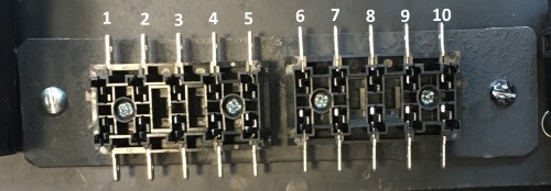
These last five wires were not in the connector but had to be wired as shown. The following table shows the two fuse blocks and how they are wired up. The photo below shows the numbering scheme on the blocks.
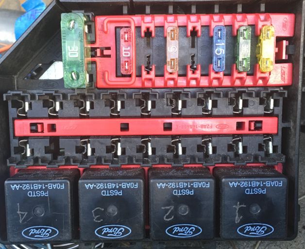
Finally there is the relay box in the middle of the boot. This is used to control the feeds to the fuel pump and the PCM, both of which require relays. Two of the relays remain open as does most of the fuse slots. This gives room for future expansion.
Here's a shot of the relay box mounted in the Pantera.
As you can see, the relays are numbered from right to left 1-4. The fuses are numbered from right to left, 1-8 (Fuse #8 is the 30A). The table below shows how it all is wired up.
I know this is a bunch to digest but all I know it works. What I did to try and help me make sense of it all was to make my own wiring diagram. The graphic below shows it all brought together.
The wiring was a multi-month process. What I'm going to do here is to highlight the end result. I'll show you all the relays, connections, fuses and other wiring issues I had to deal with to make this think go.
As you may remember, I decided to work this Coyote swap on a budget. I bought the engine out of a totaled 2012 F150 for just around $3700. The engine came with the AC pump, Alternator, Computer, and Engine Wiring Harness. I had to find the other two harnesses/connectors from online sources and junk yards. I was able to get both harnesses for just under $150.
I also bought a 2012 Coyote wiring book from Ford. This thing is a real pain in that wiring is broken down into smaller components so you are required to flip from page to page trying to ID all the connections that need to be made. I was also able to get a more usable wiring diagram from a friend of mine that made tracing wires a bit easier. Between the two resources I was able to fabricate all the wiring connections and runs necessary.
Keep in mind, my car is a junk yard rescue. Everything was missing in my car. Not a single wire was there so I had to run everything. My routing might not be stock but I had to make do with trying to figure out how to get my wires from point A to point B on the car. For all you lovers of everything stock, I'm sure what I did will end up pissing you off, but necessity is the mother of invention and I was presented with a whole lot of necessity with my car.
The basic wiring kit I used is from a company called Hot Rod Wires. See my post called Wiring for details on this process. I decided to use the front boot as my main wiring junction. I fished all my wires to the Hot Rod Wire fuse box and mounted it to a custom made "shelf" in the very front of the nose. This shelf will hold all the other components (rely boxes and other fuses) that I will need to make this thing come to life. Here's a shot of what I made with everything mounted in place.
I'll take time to explain what everything does as I present more of what I did to get her wired up. Starting from the passenger side you have the Hot Rod Wire fuse box, an additional fuse box controlling much of the engine wiring and two relay/fuse boxes. These boxes were pulled from early 2000's Mustangs from a junkyard near me. I rewired them to make them work for what I needed in the Pantera. Also refer to the earlier post called Wiring where I explain how I wired up the headlight doors using the junkyard relay box shown on the far side of the picture above.
I decided to mount the computer on the firewall I built behind the driver's seat in the engine bay. This gave me a good place to run all the necessary wires to the computer and made the harnesses fit just right. I had to do quite a few wire connections to get her all hooked up. I will do my best to present all the wiring connections needed to make the Coyote start up.
Here's a picture of the computer mounted in place. Keep in mind I haven't take the time to pretty up all the wires. That will come much later when I know I won't be needing to run any more wire. One day it will look much less of a rat nest. I have learned from past wiring projects, don't tie everything off until you are sure you are done running wire. Otherwise your nice neat bundles start to look like a bad hair day.
Now for some wiring info. I created a couple table showing the wiring harnesss for the Coyote. I pulled some of this info off various sites and modified to add what I did to get it wired up. The first one is what I call the 581Harness from Ford. This one is the non-engine wiring harness. It is a 70 pin connector. The following table highlights what each pin is wired as out of the connector from Ford and what wires I connected to that pin. Where the pin is struck through is pins that I'm not using. The Dia Page column shows what page the connection can be found on in the Ford Wiring book mentioned earlier. The notes give more detail on what this pin does and how I wired it up.
| Pin No | Ford Color | My Color | Dia Page | Notes |
| 2 | BLU | LTBLU-RD | 24-5 | MAF - LTBLU/RD->PK/LTBLU 8 conn->BRN/GRN ->MAF conn pin 4 |
| 5 | PUR-GRN was suppose to be PNK | PNK-BLK | Ford racing pcm 70 way plug | ftom LT-BLU on VSS (speed sensor switch) WHT wire VSS out |
| 7 | YEL | N/a | 20-1 | START - 85 on starter relay (non S-Terminal) |
| 10 | YEL-VT was suppose to be GRY- WHT | YEL-WHT | Ford racing pcm 70 way | CTO Clear Tach Out - front dash where tach will go |
| 12 | WH-BN | N/a | 54-3 | 85/86 AC Clutch Relay |
| 13 | VT-WH | Tan | 24-10 | Brake Pedal Position Switch - other side off switch WH wire 511 circuit of ignition switch |
| 14 | VT | YL-LtBLU | 12-1 | Regulator ALT to #1 on alt conn |
| 16 | BLU-WHT | PURPLE | 20-1 | START - Ignition Switch Start Only Purple wire from Hot Rod Wire Harness 15a fuse#10 in two small fuse boxes in front boot |
| 17 | GN-BU | N/a | 24-5 | Ambient Air Temp |
| 18 | WH-BU | BL/BLU-same as 34 | 33-1 | 85 Cooling Fan and HS Cooling Fan Relay tied to 34 |
| 19 | YE-OR | YEL | 24-9 | FUEL PUMP mod conn pin3 |
| 20 | GN-BU | N/a | 24-3 | EVAP CANNISTER |
| 21 | VT-GN | LtBU | 24-9 | From 87 of Fuel Pump Relay PLUS feeds light blue on 4 wires of 508 harness PLUS pin 1 of fuel pump mod |
| 23 | GY | N/a | 30-6 | Tow Haul |
| 24 | GN-VT | N/a | 30-6 | Oil pressure switch don't need |
| 28 | YE-OR | YE | 24-8 | ACC Pedal |
| 29 | BU-WHT | LtBU | 24-8 | ACC Pedal |
| 31 | VT-OR | N/a | 24-5 | AC Transducer |
| 32 | BN-WH | BN-WHT | 24-9 | FUEL PUMP mod pin 7 |
| 33 | VT-GRN | N/a | 24-10 | Generator Current Sensor |
| 34 | GN-BU | BL/BLU-same as 18 | 33-1 | 85 Cooling Fan Low Speed tied to 18 |
| 35 | VT-OR | OR | 24-3 | PCM WAKE - Hot At All Times 10a fuse #6 in fuse box in front boot |
| 37 | WH-GR | N/a | 20-1 | |
| 38 | BN-YE | BRN/LTBLU | 54-3 | 85 PCM Relay#4 Front Middle Power Dist Box |
| 40 | YE-VT | WT-BLU | 24-5 | MAF - WHT/BLU->GR/OR 8 conn->OR/WHT->Pin 5 MAF conn |
| 42 | GY-BN | OR-BLU | 24-3 | Hot Start or Run PUR wire fuel pump circuit HRW - 5a fuse#9 in two small fuse boxes on computer housing |
| 44 | VT-GRN | VT-OR | 24-8 | ACC Pedal45 - twisted with 45 |
| 45 | GN-OR | VT-BU->GR-BU | 24-8 | ACC Pedal - Twisted with 44 |
| 46 | VT-OR | N/a | 24-10 | Brake Pedal Position Switch/ leave open |
| 47 | VT-GY | LTBR-YE | 24-5 | MAF - LTBLU/YEL->PK/GRN 8 conn->GRY/BRN->MAF Pin #2 |
| 48 | GN-BN | ? | Cruise Control | |
| 50 | BK-YE | BK-WH | 24-3 | GROUND |
| 52 | YE-GR | N/a | 24-5 | A/C Pressure Transducer - |
| 53 | BU-OR | WH | 12-1 | Regulator - hook to pin #2 on alt conn |
| 56 | YE-VT | N/a | 24-5 | SIGRTRN |
| 58 | WH | PINK-GRAY | 14-3, 4 | Data link connector odb2 pin 14 |
| 59 | WH-BU | PINK-BLU | 14-3, 4 | Data link connector odb2 pin 6 |
| 60 | YE-GRN | WH-OR | 24-8 | ACC Pedal - Twisted with 61 |
| 61 | BU-GRY | GRY-OR | 24-8 | ACC Pedal - Twisted with 60 |
| 62 | YE-RED | BL-WH | 24-3 | Hot All The Time - 10a fuse #7 Rear Fuse Box by drivers rear tire |
| 63 | BRN | N/a | ? | Computer Data System, Cruise Control System |
| 64 | WH | N/a | ? | Computer Data System, Cruise Control System |
| 65 | VT-GR | N/a | 24-9 | Fuel Tank Pressure Sensor |
| 66 | BN-BU | N/a | 24-9 | Fuel Tank Pressure Sensor |
| 67 | YE-GY | White | 24-3 | Hot Start or Run 87 PCM Relay - 15a Fuse #1 two small fuse boxes on computer housing - tied to 68 below |
| 68 | YE-GY | Same White above | 24-3 | Hot Start or Run 87 PCM Relay - 15a Fuse #1 two small fuse boxes on computer housing - tied to 67 above |
| 69 | BK-YE | BK-WH | 24-3 | GROUND |
| 70 | BK-YE | BK-WH | 24-3 | GROUND |
| 4 wire conn | LtBLU | BLU->PK/LtBLU 8 wire conn->LtBLU 4 wire | ||
| 4 wire conn | VIO | 15a Fuse #3 two small fuse boxes on computer housing->WH/GR->8 wire conn->WH/GR->VIO 4 wire 581 harness | ||
| 4 wire conn | LtGRN | 15a Fuse # 5 two small fuse boxes on computer housing->GR->8 wire conn->LtGR 4wire on 581 harness->GR/OR 8 wire conn | ||
| 4 wire conn | GRAY | LtBLU/WHT 8 wire conn->LtBLU/RD-> signal side of oil pressure gage in cockpit | ||
The engine wiring harness is almost completely wired to the connector. Only the 4 wires shown above had to be connected from the 581 harness to the engine harness. The explanation above shows how I did this.
Then there is what I called the 15525 Harness. This normally would have gone to the transmission and to other components like the O2 sensors. Most of these wires go unused but some have to be connected. Here's a table like above showing how I wired this up. Again, the items that are crossed out are not used in my application. The wires are long enough to hook directly up to what I need them to go to so the Ford Color is the same as My Color when it comes to the wiring.
| Pin No | Ford Color | My Color | Dia Page | Notes |
| 1 | WH-OR | 30-5 | TSS - Pin 1 on round plug | |
| 3 | VT-GRN | 30-5 | TSS/OSS PWR - Pin 12 on round plug | |
| 4 | BN-VT | 24-7 | 5 Wire HO2S #1 - Right side looking from rear of engine | |
| 7 | BLU-empty? | 4of9 | REVERSE LIGHT SWITCH | |
| 10 | BN-WH | 30-5 | SOL PRES CTRL #4 - Pin 10 on round plug | |
| 11 | GY-YE | 30-5 | SOL SHIFT LOW SIDE - Pin 8 on round plug | |
| 12 | VT | 30-5 | PMW OUTPUT - Pin 4 on round plug | |
| 14 | BR-GN | 30-5 | OSS - Pin 15 on round plug | |
| 15 | GY-BU | 24-7 | 5 Wire HO2S #1 - Right side looking from rear of engine | |
| 16 | BN_BU | 24-7 | 5 Wire HO2S #2 - Left side looking from rear of engine | |
| 17 | GN | 24-7 | 5 Wire HO2S #1 - Right side looking from rear of engine | |
| 18 | YE-GN | 24-7 | HO2 4 wire Grey Plug | |
| 19 | BLU-OR | 4of9 | CLUTCH PEDAL SWITCH | |
| 20 | BN-YE | 30-5 | TRANS FLUID TEMP - Pin 7 on round plug | |
| 21 | GN-VIO | 4of9 | CLUTCH CRUISE CONTROL RELEASE | |
| 24 | GN-BN | 24-7 | 5 wire HO2S #1 - Right side looking from rear of engine | |
| 26 | GR-WH | 24-7 | HO2S SIGTRN - Ground? | |
| 27 | WH | 24-7 | HO2S 4 wire Grey #2 | |
| 28 | WH | 24-7 | 5 Wire HO2S #2 - Left side looking from rear of engine | |
| 29 | BN-YE | 24-7 | 5 Wire HO2S #1 - Right side looking from rear of engine | |
| 33 | BN-GN | 30-6 | TOWS & TRANS CONT SWITCH | |
| 34 | YE-VT | 30-5 | SOL PRES CTRL #5 - Pin 16 on round plug | |
| 35 | GY-VT | 24-7 | 5 Wire HO2S #2 - Left side looking from rear of engine | |
| 38 | GRY-VIO | 4of9 | REVERSE LIGHT SWITCH SIGRTN | |
| 39 | WH-GN | 24-7 | 5 Wire HO2S #2 - Left side looking from rear of engine | |
| 40 | VT-GN | 24-7 | 5 Wire HO2S #2 - Left side looking from rear of engine | |
| 41 | BN-BU | 30-5 | TRANS RANGE SIGRTN - Pin 11 on round plug | |
| 43 | BU-GR | 30-5 | SOL PRES CTRL #1 - Pin 9 on round plug | |
| 44 | GN-BN | 30-5 | SOL PRES CTRL #2 - Pin 14 on round plug | |
| 45 | GR-OR | 30-5 | SOL PRES CTRL #3 - Pin 13 on round plug | |
| 46 | BU-GRY | 30-5 | SOL PRES CTRL #6 - Pin 3 on round plug | |
| 47 | WH-OR | 24-7 | HO2S 4 wire Grey #1 | |
| 49 | BU-WH | 24-7 | HO2S 4 wire Grey #2 | |
| 50 | BU-GN | 30-5 | TRANS SOL PWR CTRL - Pin 7 on round plug | |
| Not in Conn | BL-BRN | GR-OR Through flat 8 wire Ford conn | 24-7 and 3/9 | 6 wire black conn HO2S power coming from fuse5 on two fuse blocks in front boot, green wire 15a |
| Not in Conn | OR-GRN |
OR -> FLAT 8 wire -> OR-GRAY
| MAF power | |
| Not in Conn | PK-BLU |
BLU-RD->flat 8 wire Conn->BRN-GRN
| MAF | |
| Not in Conn | PK-GRN |
TAN-YEL->Flat 8 wire conn->GRAY-BL
| MAF | |
| Not in Conn | GRN-OR |
WHT-BLU->flat 8 wire conn->WHT-OR
| MAF |
These last five wires were not in the connector but had to be wired as shown. The following table shows the two fuse blocks and how they are wired up. The photo below shows the numbering scheme on the blocks.
Fuse 1
|
15a
|
Power In Jumper 1-5 off 87 of PCM relay.
Out, White->Pin 67&68 of 581 harness
|
Fuse 2
|
15a
|
Power In Jumper 1-5 off 87 of PCM relay.
Out, PNK/OR->OR/GRN 8 conn->GRY/OR->MAF power pin 3 MAF conn
|
Fuse 3
|
15a
|
Power In Jumper 1-5 off 87 of PCM relay.
Out, GRN/YEL->GRN/BLU->WH/GR->WH/LtBLU 8 wire conn->VIO 4 wire 581
|
Fuse 4
|
10a 13-5
|
Power In Jumper 1-5 off 87 of PCM relay.
Out, Tan->86 of Cooling Fan Relay#3 in front power box
|
Fuse 5
|
15a
|
Power In Jumper 1-5 off 87 of PCM relay.
Out, YEL->YEL/BLU->GR->GR/OR 8 wire conn->LtGR 4wire on 581 harness
|
Fuse 6
|
10a
|
Power In BLK/YEL from hot thd stud on Alt - Hot at all times - Out, OR->VT/OR Pin 35 581 Harness
|
Fuse 7
|
10a
|
Power In BLK/YEL from hot thd stud on Alt - Hot at all times. Out, BLK/WHT->YEL/RD Pin 62 581 Harness
|
Fuse 8
|
Empty
| |
Fuse 9
|
5a
|
Power In YEL/GRN hot start and run off ignition switch
Out, 5a->OR-BLU->pin 42 581 harness
|
Fuse 10
|
15a
|
Power In, PUR Start only HRW Harness through 15a fuse Out, PUR->BLU-WHT Pin 16 581 harness
|
Finally there is the relay box in the middle of the boot. This is used to control the feeds to the fuel pump and the PCM, both of which require relays. Two of the relays remain open as does most of the fuse slots. This gives room for future expansion.
Here's a shot of the relay box mounted in the Pantera.
Fuse 1
|
WH/RD - Feeds #3 on Alt Conn
|
10a fuse
|
Fuse 2
|
Feeds 30 on relay 2
|
open
|
Fuse 3
|
Feeds 30 of relay 3 - Fuel Pump Relay
|
15a fuse - fuel pump
|
Fuse 4
|
Empty - no wires
|
n/a
|
Fuse 5
|
OR->TAN
|
15a fuse - To data link connector (ODB test port) Pin 16
|
Fuse 6
|
Empty - no wire
|
n/a
|
Fuse 7
|
BLK/WHT wire
|
n/a
|
Fuse 8
|
Feeds 30 and 86 of relay 4 - PCM Relay
|
30a fuse
|
Relay 1
|
|
not used now
|
Relay 2
|
|
not used now
|
Relay 3
Fuel pump
|
|
Fuel Pump Relay
|
Relay 4
PCM
|
|
PCM Relay
|
I know this is a bunch to digest but all I know it works. What I did to try and help me make sense of it all was to make my own wiring diagram. The graphic below shows it all brought together.
Anywhere you see Start Only or Start/Run Only, this was hooked up to the Hot Rod Wire system coming off the ignition switch I modified for the Pantera. See my separate post on wiring up the modular ignition switch I used for this project.
The last thing that I had to to was to pay someone to turn off many of the circuits in the computer that I wasn't using. I believe that there is a lot of anti-theft components in the original wiring that I'm not using. When I went to first start the Pantera, all the engine components (injectors, coils, fuel pump, etc.) went completely dead. In the Run position it all showed hot, but in the Start position, nothing. After a bunch of wire tracing and reconfirmation I had the wiring right I found out that the computer was shutting everything down because it sensed too many things missing in my setup.
When all the extra components were turned off in the computer (I'm not sure I'm using the right terminology but that's what I think was done), the cart fired up right away!
Here's a link to a video of that amazing day. Keep in mind this is the first time in over a year the engine had been started. It cranks a bit before firing up but that's because the fuel system and everything was never tested. She now cranks pretty quickly. It still needs to be tuned for idle and proper accelerator pedal sensitivity, but as of this date it is running amazingly well for having been transplanted like it has been.
Video Link
https://www.youtube.com/watch?v=QJtKOvW2XI4
Subscribe to:
Posts (Atom)