Sunday, September 22, 2013

Master Cylinder, Brake Booster, Pedal Assembly

The master cylinder/brake booster combination I choose was one for a GM that I found on Summitracing.com. Here's the page that links right to what I bought. http://www.summitracing.com/parts/clp-8dsrb-mc-c/overview/

The assembly is a Classic Performance universal system (P/N 8dsrb-mc-c). It has an 8" dia dual booster and two chamber universal M/C. It comes with a little chrome to boot. I think the entire set up cost just under $300. Not bad at all.


The Pantera mounting plate would have to be modified to fit the good old US 4 bolt pattern on the back of the booster. Other than that it looks to be a pretty straight forward install.

I began by rebuilding the pedal assembly. Unfortunately the torsion spring on the clutch has snapped on my assembly. I checked around and found one online for some god-awful price (with an even worse shipping price). My stubborn nature kicked in and I refused to order the stupid thing. I thought that I would resort to hooking up a simple tension spring to return the clutch if I couldn't find something that would work.

After a couple weeks of checking here and there for a torsion spring that would work on the clutch I was giving up hope. My pride just wouldn't let me purchase the original equipment one that was being extorted online. Then my buddy was showing me an old Singer sowing machine table from the 40's he was getting rid of. He was messing around with this lever that was spring loaded to return to a certain position. The light bulb went off in my head. I looked closely and found that a torsion spring was used to return this lever - one that looked like it would work on the Pantera.

I took the spring out and did a bit of bending, cut out a couple coils and wouldn't you know it - it works great. Now I have the starts of a real rat-rod Pantera! Singer sowing machine- who would have guessed.

Here's a picture of the pedal assembly assembled and ready to go (minus the gas pedal which I didn't attach for the picture). If you look close you can see the spring on the clutch pedal - a bit too big but should be just fine for now.


As I said earlier, the mounting plate needed to be modified to mount the booster I choose. I made a wooden template and used it to locate the mounting holes I needed to put into the plate.


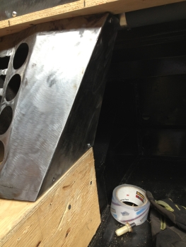
After drilling the holes I decided to make a 1/4" steel plate just like the wooden template to give the mounting locations a bit more strength. I sandwiched the plate between the back of the booster and the mounting plate on the Pantera. Here's a couple pictures of the booster mounted to the mounting plate. 


I was just about to mount the completed assembly into the Pantera when I decided to make a spacer to extend the pedals a bit more to give me some additional leg room. Here's the spacer I made out of 1" square tube. This gives me one more inch of leg room down by the pedals - good for my 6'5" body!!!


I had to drill out the mounting holes on the Pantera body to get the bolts to work properly. Once that was done it was a pretty easy matter of just bolting up the assembled system. I did have to remove the clutch pedal, slide the pedal arm towards the passanger side of the car and wiggle the entire assembly into place. Once it was in the hole I had to reconnect the clutch pedal and start to bolting up the assembly to the car.

Here's what it looks like in place. 


Here's a view from inside the car. I did have to do a little reshaping of the clutch pedal to avoid contact with the steering shaft. All in all, not too tough a project. 


After getting a few more connectors it was time to hook up all the lines I had been running for the brakes. I mounted a "T" and the Proportioning Valve on the wheel well just to the outside of the master cylinder. Hard lines were bent and connected to hook the master cylinder up to both the hard lines under the Pantera running to the front and real wheels. Here's a couple pictures showing you the lines that were added. 


Now the entire brake system is plumbed. I will have to wait on the rebuild of the rear knuckle before I can fabricate the brackets needed to install the rear brakes. After that it is ready to add fluid and can actually stop on its own! Big steps forward. 


Front Brake Lines

The front lines were a bit more of a challenge to figure out where they are to be routed to. I ended up not liking the fact that the passenger side line actually runs through the boot. There is so much room up under where the battery is located (under the boot) that I decided to run the lines through there. Here's some pictures of how the front lines look.


In the picture above you see the front and rear lines coming together up against the bottom of the front boot. These lines will be connected to the hard lines that will come off the master cylinder - to be plumbed up later. 


Thursday, September 19, 2013

Rear Brake Lines

Finally got most of the parts needed to start plumbing in the brakes. All the lines were missing and I wasn't sure how to run the lines to the rear. I was particularly worried about how to place the lines near where the transaxle will be sitting. Then it was the Internet to the rescue.

Thanks to the owner of Pantera 2077. He has a blog highlighting his restoration on blogspot.com. This page shows the rear brake line routing in detail. http://pantera2077.blogspot.com/p/chassis.html. I ran my line as close to this as possible. 

I did have to drill a hole in a cross member near where the engine will sit. Looks to me like the cross member on my Pantera was replaced. No big deal. Drilled out a set of clearance holes to feed the line through and it was ready to go. 

I decided to run 3/16 stainless for the entire car. I also elected to use AN fittings (-3) throughout. I purchased a Rigid flaring tool (37 degree) to custom make my lines. The tool was more than I wanted to pay but I'm sure glad I got it - it works great. I think I paid about $130 for it. 

What I was able to get done today was to run a single line from up under the front boot back to the rear of the car. I took a bit of bending here and there but I was able to get a single line for this long run. Here's some shots of what it looks like now. 


This is a shot looking up from under the front boot. The three holes just beyond the end of the tubing is where the brake lines will be coming down from the Master Cylinder. I will be attaching another line holder up towards the top of the line after I figure out how I'm going to run the line up from here to the MC.


Here we are looking from the front of the car to the rear. I will need to get a couple more grommets to protect the line in the middle pass through hole. The line is nice and secure and looks pretty much like the original.


Now we are looking from the rear of the car. you can see the cross member in the middle of the shot where I had to drill some pass through holes. The same will need to be done for the rest of the pieces that will come back to the transaxle and for the e-brake cable. 


Here we are looking at the passenger rear side of the car. The line ends at a T. From here I will hard line up to the small hole at the top of the picture where a flex line will go to the caliper itself. 


Next I made the tubes from the T to the hole in the fenders to where the flex line will go to the calipers. Here's what they look like. Pretty close to the originals from the pictures I have seen.


Monday, September 16, 2013

Console Finishing

I covered how I framed out the dash and console in an earlier post. Now its time to get the console in a finished looking state. I've decided to fiberglass over the wood and to smooth it out from there. I have never really fiberglassed anything of importance before so it was off to the Internet to learn some basics.

After a bunch of You-Tube videos and visiting various fiberglass product sites I settled on ordering 1.5 ounce cloth and a poly resin from FiberglassSite.com. They had about the best price per yard on the cloth and a decent resin cost. I paid less than $3/yrd on the cloth and about $37 for the resin (one gallon with hardner). Shipping was a whopping $33! Ouch.

I prepped the console by giving it a rough sanding. I rounded all the corners and edges as well. I also decided that I needed more room on the side of the console where the e-brake handle is. I did a bit of cutting and repairing to give me an indent where the handle will sit.


Then I just got with it and fiberglassed the entire box. I decided I wanted some thickness to the fiber so I went 3 layers. Overall it came out pretty good.

Once dried I found out how many bubbles and bad spots I had allowed to happen. I think I was in too big a hurry to get the cloth laid down and didn't prepare enough beforehand. I think when I go to do the dash I will cut out the cloth exactly as I want it to lay and then cut out two more exact pieces. Then I won't feel as rushed between layers trying to cut and mix the resin at the same time.


By the way, I found it best to mix 10oz of resin at the most at one time. The resin tried to set up on me in my paint can before I could get the resin on the cloth. More than 10oz was a waste since I ended up tossing out some of it anyway.

After letting the cloth dry for a couple days I started the finishing process. Out came my 4" and 6" Random Orbital (RO) sander, a small hand sander and my grinder with a 36 grit layered grinding disk. First step was to cut off the edges. I used a grinder with a cut off wheel for that. Then I started the real work.

With the grinder and the 36 grit layered grinding disk I wend over one side at a time. I was looking to eliminate all the bubbles (by grinding them into a hole) and to knock down as much of the high spots as possible. This isn't a very exact process. Just whack away at it and keep feeling for high spots and look for bubbles. You can see the grinder and grinding wheel I used to do this step - remember this is just a really rough outcome. Once I felt like it was fairly uniform it was time for the bondo.


I mixed up small batches (3 golf ball blobs) at a time. I quickly coated the side that I had just ground, doing my best to give a uniform, relatively thin coating.


After about 25 minutes dry time I roughed up the fresh bondo with a rasp and then got out my 6" RO sander and used 60 grit paper. I found this combination of sander and paper gave me a quick, smooth finish.


Of course there are many low sposts that didn't get quite enough bondo so it was back to applying bondo to the low spots. Here's a closeup of a bubble that needs to be ground out and finished with another coat of bondo.


After about three rounds of bondo/sanding it looked really great. The edges and rounded spots is where you need to pull out all your sanding tools. I used soft pads with various grits of paper to try and give myself a uniform edge and radius where needed. Take your time here since this will show up the most when a gloss paint is applied.

I continued the same process on all sides of the console. It came out pretty smooth. I put a little primer on it to help me see any spots that need a little more attention. Not bad for my first attempt at fiberglass.


Wednesday, August 14, 2013

Front Brakes

After a ton of research on the Internet and through the various Pantera forums I finally settled on a Wilwood brake set for the front of the Pantera. Apparently the Wilwood Part No. 140-11072 kit for a 1966 Mustang fits the Pantera spindle. This kit comes with all parts (minus flex lines and banjo bolt) for the front brake system. Total cost on the Wilwood site, around $875 plus shipping.

I got on Ebay and searched the Wilwood part number and found a new kit being sold for $737.49 with free shipping. I figured I saved close to $200 bucks going this route. Not a bad deal at all.

The kit came and it was all new parts, with the exception of one bracket that looked like it had been opened and scratched up a bit. Probably how I got such a great deal. All other parts were sealed in the original plastic bags and good to go.

First think I did was remove the original hub that came with the Pantera to expose the spindle. Here's a before and after of the passenger's side.


I took out the scratched up mounting bracket from Wilwood and held it up to the spindle - PROBLEM! The mounting surface holes are way too big for the bolt pattern on the spindle of the Pantera. Second problem (so I thought) the 3.5" caliper mounting arm won't fit over the 3" original ears shown on the right picture above. Solution to problem No. 1 - make a new mounting bracket and use the 3.5" caliper mounting arm from Wilwood. Solution to problem No. 2 - mount the caliper on the front side of the spindle rather than the back as it was stock (or cut off the ears on the Pantera spindle).

Here's a picture of the problem. You can see how the four mounting points on the spindle don't align with the various holes in the Wilwood bracket. But, by removing the four smaller bolts on the right side of the bracket in the picture below the caliper mounting arm can be removed. The picture below shows how the caliper will point toward the front of the car.


I decided to mount the bracket with the caliper going forward so I could use the original ears as two more mounting points. Unfortunately the two spindle bolts (actually one bolt and one bolt hole) can't be used to hold the bracket to the spindle. They are in a position that will hit the hub if you let the bolt hold down the mounting bracket. The two lower bolts are out of the way and will work fine. I want more than just two bolts holding this bracket in place - why not use the original ears that held the original caliper in place as mounting bolts - that can be built into the new bracket I will need to make.

So, after a trip to the metal shop, I had the aluminum plate needed to make the new mounting bracket. I purchased the same thickness aluminum that came with the Wilwood kit. After mocking up what the new bracket should look like I cut it out and drilled all the mounting holes for the caliper arm. Here's a picture of the new bracket roughed out with the caliper arm holes already drilled.


 Next I drilled out the center hole to fit over the spindle. It measured 1 3/4" on the Pantera so I decided to cut the hole 2" for clearance. Once the center hole was drilled out I clamped the bracket to the spindle and used the original bolts on the spindle to mark where to drill the mounting holes. To do this I used the old paint trick. I put a dab of paint on the end of a bolt , put it in the spindle mounting hold and pressed it against the clamped mounting bracket. I did this with all the holes on the spindle and the two holes on the ears for the old caliper mounting point. I then went to work and drilled them all out. Here it is completely drilled and with the edges rounded a bit.


Notice the larger mounting hole near the center left of the bracket above. I drilled this hole larger to fit over the head of the bolt on the spindle that would interfere with the hub if I were to use it to mount the bracket. Basically the bracket above is turned up side down. The large hold near the center left is actually for the upper left side mounting bolt on the spindle (see an earlier picture of the bolt pattern on the spindle). Though this won't hold the bracket in place it will help keep it from moving since the bolt head fits tight into this larger hold size.

Next I test fit the bracket and made a mirror image of it for the driver's side. All's well - right? Well not so much.

I put a little paint on the bracket, assembled the caliper mounting arm with the four bolts it came with and put the bracket on the car. Here's what it looks like.


Looks great - right? Problem is that when you try and mount the caliper it hits the tie rod end - bummer! So I guess I need to just cut off the original ears - right? I took off the bracket and just for the heck of it mounted it with the new caliper mounting arm point backwards like it should have been in the first place. Guess what - it fit perfectly. Another case of taking time to disassemble everything and try it all for fit before making judgement about what will and will not work. When will I learn this lesson?

Here's how it looks facing the right way (after drilling another clearance hole for the top left mounting bolt on the spindle.


Now we are back to figuring out how to mount it safely to the spindle since I can't use the top two holes due to the hub interference. After playing around with the bracket a bunch I felt that it would be best to drill two holes into the bracket to mount give two additional attachment points into the original ears for the caliper. Compare the picture below to the one above to see the two holes added.


Finally I could assemble the Wilwood parts and put them on the Pantera. Looks pretty sharp!


Thursday, July 11, 2013

Dash Fab

I did a pretty exhaustive look online at the various dash styles that came original in the Pantera and decided that the 1972 look (Pod Design) wasn't what I wanted for 3854. I like the 1974+ dash much better - much simpler and very clean.

I looked all over for a dash I could purchase and still haven't found one that I wanted. I have found a couple dash options but they are either 72 models or the owner has a bunch of parts he wants to sell as a package. One guy had a dash and said I could have it and the rest of the parts from his parted out Pantera for $50k! He really likes his parts. Uh, No thanks!

After striking out I decided to fabricate my own dash and see how it looks. I'm modeling it after the 1974 dash. It won't be exactly like it but a close match - hopefully. The challenge with 3854 is that it has a roll cage installed. The cross member and uprights would have made the installation of a stock dash quite the challenge.


To get started I decided to make the top piece first. I rounded up a big piece of cardboard and began cutting out a template. This let me get the general shape and cutouts for the roll cage uprights.


Once I was happy with that I traced the template onto a piece of sheet steel and cut it out. 

 With a little trimming here and there I found this to fit really nicely. I welded up a couple brackets to the bottom and bolted it in. Unfortunately the steel was WAY too thin (I used 22 gauge to try and keep the weight down). It just wouldn't sit right in the car. So I thought about using heavier gauge metal but decided against it for now. Instead I opted for wood.

I traced the metal cutout onto a piece of 1/2 plywood and cut it out. I decided to cut the ears off where the roll cage uprights come up through the dash and will fabricate an appropriate solution around that part of the cage at a later time.

The Pantera has a slight bow to the dash mounting surface so I needed the plywood to have that same bow. I rigged up a contraption to put the bow in the plywood using a cargo strap, a couple of clamps and a piece of 2x6. With a little water on the wood and a day in the sun the bow came out perfect - Thanks Clyde Hovis (my carpenter grandfather - who showed me how to do this when he was bending planks to make a boat many, many moons ago). Here's what the wood top looks like as I was bending it.


Then I started on the top piece that goes above the tach and the speedo. I determined the angles that looked the best and cut out some triangles to give me the height I'm looking for.


Next came the top - a few cuts on some MDF and here she is.


Now I realize everything is very square - all the edges and transitions are very angular. I don't plan on leaving it that way. Ultimately I'm thinking that I will figerglass the wood. That way I can shape it any way I like. I'm a long way from doing that. As you know time usually presents the opportunity to try many, many different iterations to a project like this.

Back to the dash project. I've put it off long enough. Today I decided to mount the top into the car so that I can lay out the rest of the dash front. Putting it in 3854 is a bit challenging since a lot of surgery has happened before I got the car and I have a roll cage to contend with. So - custom brackets are the only way to go. After a bunch of measuring and remeasuring I came up with the following brackets.


The first two were pretty straight forward. I was able to capture two original mounting spots for the original dash and bracket my new top to the car. The picture below shows a closeup of these two brackets. Pretty simple stuff. 


 Not bad - a little paint and these two will be good to go. But I found that the dash was a way to easy to move up and down with these two brackets. I was thinking about making two more to tie down the passenger side. But I didn't think it would tie down the dash in a solid fashion. So, turning lemons into lemonade, I decided to make a bracket that ties into the roll cage bar that is in the way of my dash install. Below is what that bracket looks like.


Now she is locked into the car in a big way. Better yet, I can easily remove the entire dash top by taking off two bolts and loosening two hose clamps. Quick and easy. 

After I locked the top into the car, I started laying out where the dash front will be. But before I can fabricate those parts, I realized I better pick some instruments for the car since I don't have but a couple of the original gauges from 3854. Once I pick the gauges I'll be able to know if the layout is going to work or not. 

I finally settled on the SpeedHub set of 6 gauges model no. GR4-258-6 kit. They are 4" speedo and tach and 2 1/16" fuel, temp, oil pressure and volt meter. These are electronic gauges so they have a very low profile - only 1.1" is needed from the back of the gauge panel. This is great since the cross member of the roll cage is right where the gauge will set.

I decided that I really like how the 74 and up Pantera gauge cluster is angled for the speedo and tach. I used a piece of 18 guage metal to bend and shape up the basic panel where the speedo and tach will go. Here's a picture of this piece.


The shape, size and position of the gauge holes came about as I sat in the car with my head touching the roof so I could make sure I could see the gauge cluster through the steering wheel no matter where I place the seat. With my head touching the roof I only a small part of the gauge will be blocked by the wheel. I don't know if this is the case in Panteras with stock dashes, but this is the best I could get it to work for me.

Next it was time to determine how to attach the flat metal pieces to this angled section of dash. To do this I had to first remove the wooden dash top and decide where I want to the dash front to attach to it. After some measuring and eye-balling what would look best I came up with a straight line 1 1/4" from the front edge of the dash top to be where the metal will sit on the dash. I then attached a couple pieces of light weight metal 1/2" square tubing as the mounting surface for the dash front. Here's what that looks like.


I attached the tubing with carrage bolts that were counter sunk into the dash top. The hole will eventually be filled in and covered with fiberglass.


With the mounting surface for the dash front in place I cut some 18 guage metal in rectangles 5.25" wide. These pieces will be welded to the angled part of the dash front. I blended the two pieces together with triangles to give the transition a less abrupt look. Again, this is still in rough form and a bit too anguler - this will change as I refine it down the road.


Next I placed the entire thing in the Pantera to see how she looks. Not bad - still very rough but on the right track.


After looking at the dash front for quite a while I decided I didn't like the bend I put in the left side. I want the dash front to extend past the roll cage uprights. So I cut off the bent part (just can't get that straight enough again) and welded up a new end on both sides of the dash front. The front now extends all the way to the roll cage on both the left and right sides. 

Next I had to nip away at the extensions to allow it to wrap around the protruding roll cage uprights. I made a cardboard template and started carefully and slowly taking away metal. After three or for fittings I got it just right. Here's what it looks like off the car with the extensions and the cutouts for the roll cage.


Next I decided that I wanted a little wrap around to go on the ends of the dash front to finish off the look when you are looking at the dash from the outside when the door is opened. I made a template to fit around the roll cage and conform to the door pillar. I welded this to each end of the dash front with a slight angle out from the dash so that it will clear the roll cage upright. Here's what that looks like off the car.


Next I turned my attention to the bottom of the dash. I wanted it to have a lip protruding from the lower to match the look of the upper part of the dash. I decided wood would be the easiest to use to make this piece. This will ultimately be attached to the cross member of the roll cage to give the lower part of the dash the rigidity it needs.

I measured from the front of the dash to the roll cage cross member and found I had a maximum of 2.75" to work with. I ripped a piece of 1/2" wood this size and attached angle iron to them to allow the dash front to screw into it. I left just over an inch that will protrude beyond the dash front. This gives the upper and lower of the dash a bit of interest in how it overlaps the front. Here's what the bottom part of the dash looks like before it was installed.


Next comes the fun part - putting it all together. I C-clamped the dash front to the upper section just where I wanted it to be mounted. I then drilled a pilot hole followed by a clearance hole for the 10-24 allen cap screws I will be using on the dash. I then installed the 7 cap screws that will hold the top part of the dash front to the upper portion of the dash. Then I carefully held the lower portion (show above) on the dash front and drilled a pilot hole letting the point of the drill mark where the holes should be on the lower angle bracket. I then drilled the clearance holes and attached the lower to the dash front using the cap screws.

Now that it all fit properly, I had to remove some of the upper screws to allow me to remove the entire dash from the car. I want to weld the nuts for the cap screws to the upper and lower portions of the dash so that I can remove the dash front if I need to in the future.

With the entire dash assembly removed I reassembled the entire dash and carefully welded the nuts to the upper and lower dash sections. Of course a couple of the screws got splattered by weld slag and I had to redo the nut weld and/or completely replace the welded nut. Second time's a charm and it all went back together perfectly.

Finally I finished grinding off all the welds on the dash front and put it back in the car to see how it looks. I really like how this is turning out. Next comes the center console and instrument cluster face. Here's how it looks after today's work.


With the dash to the point where it is usable and adaptable for future additions, I moved on to the center console. This was a pretty simple project of just framing out the basic shape using 5/16 plywood. This too will be fiberglassed as the project progresses.

I tried to use the basic shape and style of center consoles I saw in other Pantera pictures. I made it so that I would have a more pronounced arm rest in the center where I could store items since the cross bar on the roll cage excludes me from making a glove compartment in the dash. Other than that it is pretty basic. Here's a picture of the center console installed with the gauge front in place as well. More on that project in a minute.


The gauge panel was a lot of fun to make. I was fortunate to have been given an original gauge front with the purchase of the Pantera. This at least had all the holes cut out for the gauges and buttons. I took this piece and modified it to fit my new dash design. I used the same thickness steel to weld up sides and another front for the radio and climate control mechanism to be mounted. Here are pictures of the various pieces rough welded into place. You can see from these photos all the pieces that had to be added to make the unit functional with my design of the dash and the center console. 


I then took the rough welded gauge panel and marked on the console and on the dash where it would be attached. I fabricated brackets that matched the angles of the sides, drilled mounting holes and attached the brackets to the center console (4 on the console and 2 on the dash bottom) where I could attach the gauge panel assembly. I welded nuts to the brackets so that I could easily attach and remove the gauge panel when I needed to. Once I was satisfied how it came together I ground down all the welds and mounted it to the console and dash for a final set of pictures. 


Not bad at all. It all fits really nicely. I will have to do some grinding to make room for fiberglass when it comes time for that. Not stock but close, plus it fits me much better than a stock set up would have anyway. Now comes all the work to make this angular bunch of metal and wood look like it originally came in the Pantera.

After all the fiberglass work on the dash top and console (separate posts) it's time to smooth out the dash front and the instrument cluster. These both are metal pieces that have been welded together in spots. A little bondo was needed to finish the instrument console. The dash front needs to be modified to add vents. More on that in a bit. 

Here's a couple photos of what the instrument cluster looks like smoothed out. Still a couple more applications of bondo is required to get it just right, but this is basically the finished product.